- We can match frontier performance on a small labelling task with a small, off-the-shelf image model. Trained only on labels from the robot’s logs, it scores 0.76, against 0.77–0.79 for the top frontier models.
- Model performance in simulation correlates strongly with real-world performance on our vision-based task (Spearman ρ = 0.85 across 11 frontier models).
- Improving simulator realism directly benefits real-world predictive power in our experiments. A robot model learned from video, rendered with domain randomisation, raises a render-trained probe’s real-image accuracy from 0.49 to 0.64 [0.61, 0.66]. That closes 54% of the gap to training on real footage, with significant gains on both rail position and arm reach.
Why simulation fidelity matters
Robot learning in a real lab is expensive. Runs take hours, protocols use real reagents, and mistakes break things. A simulator that faithfully reproduces the workcell lets us train and test policies at a scale the physical cell cannot support. But a policy trained in simulation inherits every way the simulation differs from reality. At Gamow Labs, we are building toward autonomous experimentation, which depends on simulated environments robust enough to produce results that hold up out of sample on real hardware. This post presents our latest results on improving the realism of our simulator.
The SIMPLER paper (Li et al., CoRL 2024) showed that simulators matched to real setups can rank manipulation policies in the same order as real-world evaluation, and introduced MMRV to measure how costly ranking errors are. We apply the same methodology to perception, and add a second question SIMPLER did not ask: does the simulator also produce training data that transfers?
We test our simulator environment on three axes:
- Motion fidelity. Does the twin move the way the real robot moved?
- Evaluation fidelity. Does the twin rank models the way real footage does?
- Training fidelity. Does a model trained on the twin’s renders perform on real footage?
The workcell
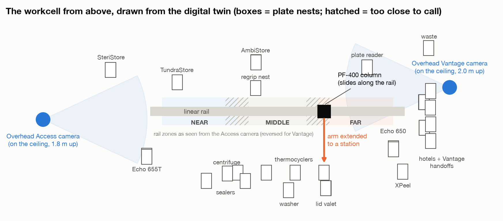
The cell is a long, narrow room lined with instruments. A Precise PF-400 plate-handling arm rides a linear rail down its centre: a vertical column travels along the rail, and a jointed arm extends to pick and place microplates at instrument nests. Our scheduler, GBG, sends the robot joint-space moves and gripper commands and logs every command and reply.
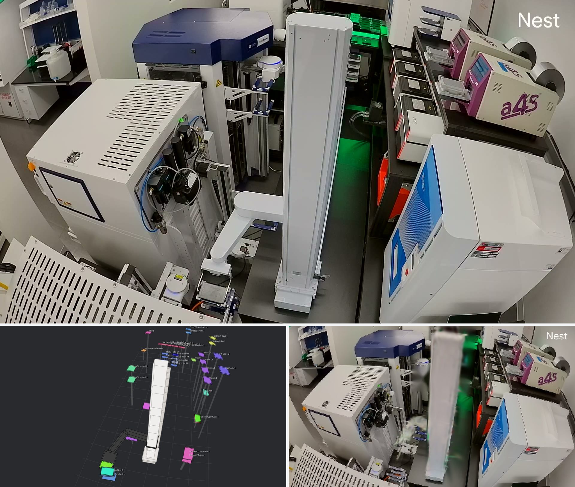
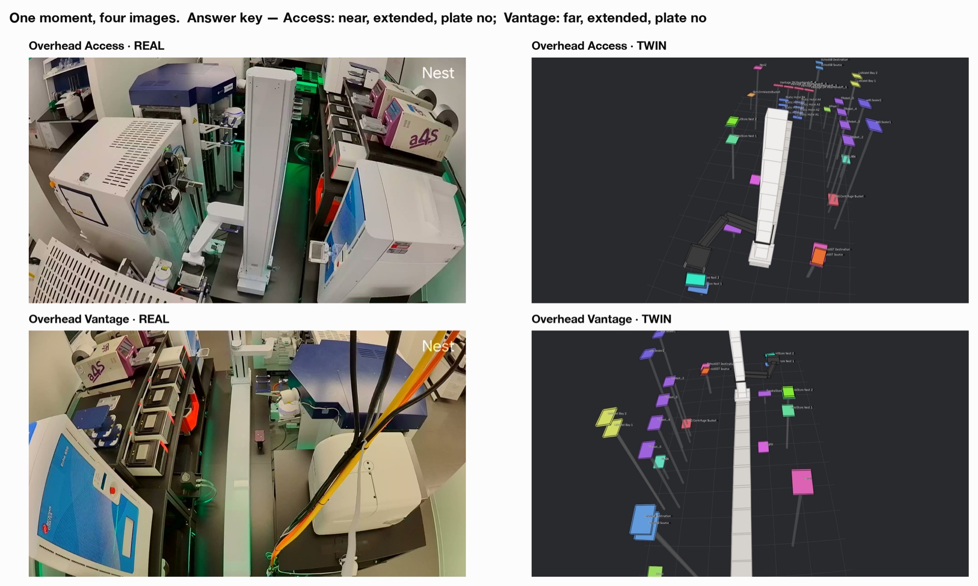
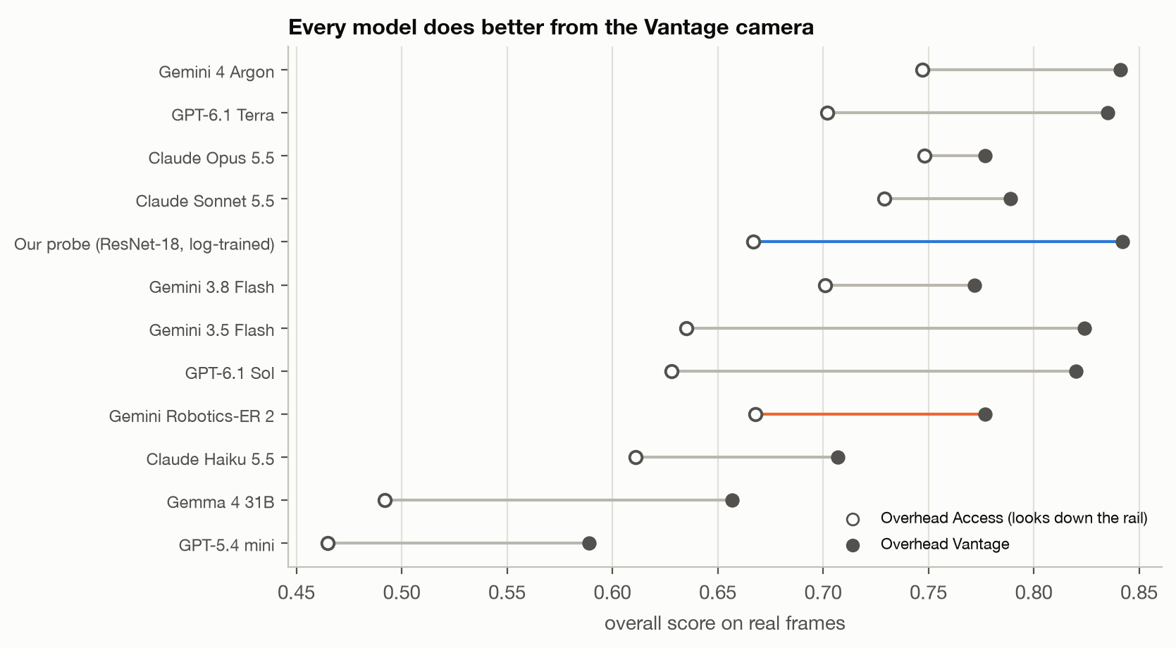
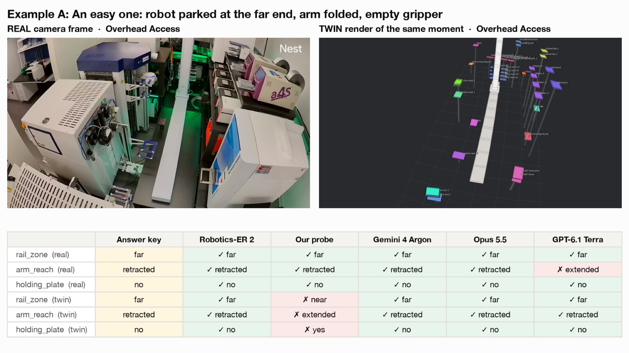
Two consumer fisheye cameras (Google Nest) are mounted on the ceiling at either end of the rail, which we call Overhead Access and Overhead Vantage. Our digital twin reproduces the cell’s layout and the robot’s kinematics, replays the logged motion, and renders it through calibrated models of both cameras.
LabRobotBench: ground truth from robot logs
Motion fidelity
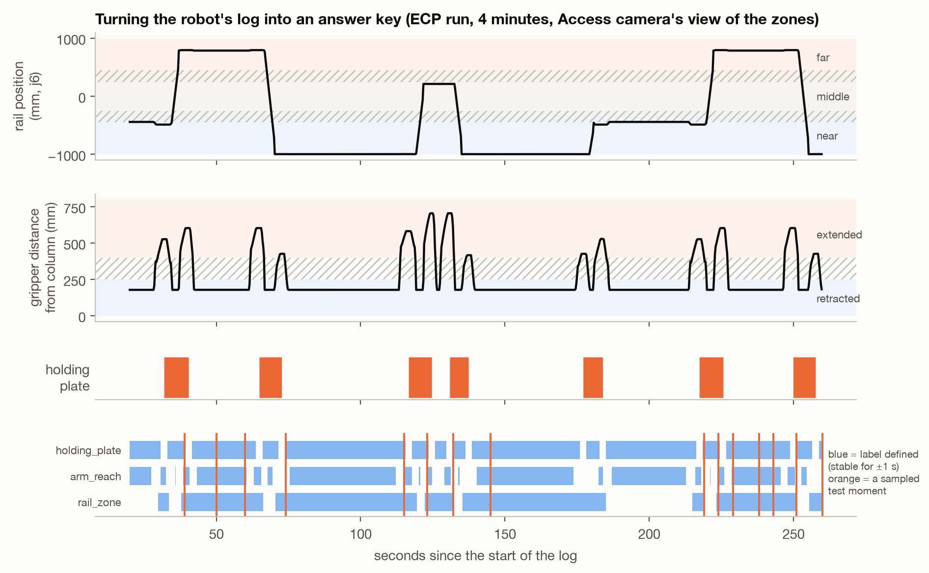
Each move command specifies target joint angles and a rail position. We replay these into a piecewise-linear joint trajectory and track plate custody from gripper-close and gripper-open events. Against the controller’s own end-of-move and position replies, the replayed timing has a median error of 0.015–0.022 s and the rail position a median error of 0.02 mm. The twin’s kinematic state is a faithful record of what the robot did.
Clock alignment
Labels are only as good as the alignment between camera and controller clocks. We compute per-frame motion energy from the video and cross-correlate it with logged motion, shifting in 0.25 s steps. All six run and camera pairs peak within 0.25 s of zero.
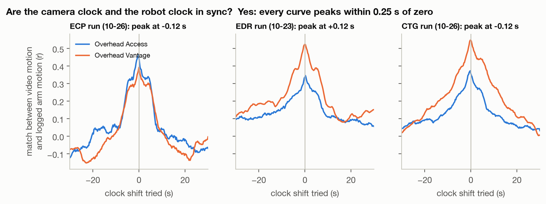
To keep labels robust to any residual offset, we only score a question at a moment when its answer holds for 1 s before and after.
Tasks
We ask three questions of every image:
| Question | Classes | Label rule |
|---|---|---|
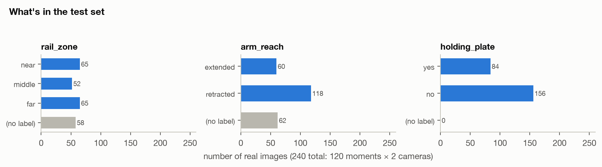
| Rail zone | near · middle · far (relative to the camera) | Rail thirds; excluded within 10 cm of a boundary |
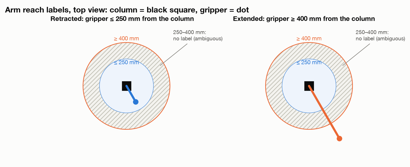
| Arm reach | extended · retracted | Column-to-gripper distance ≤ 25 cm is retracted, ≥ 40 cm is extended; excluded in between |
| Plate held | yes · no | Between a logged grip and the following release |
Test set
We filmed three mock protocol runs on 23 and 26 October 2026, about 2.5 hours of video. From these we sampled 120 moments, 40 per run and at least 5 s apart, oversampling rare states such as the arm extended or the robot mid-rail. Each moment gives four images (real and twin, from both cameras), for 480 images in total.
Models
We evaluate eleven zero-shot vision-language models and our own probes: small image classifiers trained on labels from the robot’s logs.
| Family | Models |
|---|---|
| Gemini Robotics-ER 2 (preview), Gemini 4 Argon, Gemini 3.8 Flash, Gemini 3.5 Flash, Gemma 4 31B | |
| Anthropic | Claude Opus 5.5, Claude Sonnet 5.5, Claude Haiku 5.5 |
| OpenAI | GPT-6.1 Sol, GPT-6.1 Terra, GPT-5.4 mini |
| Probes (ours) | Frozen ResNet-18 (ImageNet) features on a 3 × 5 spatial grid, with a logistic-regression head; trained on real footage or on simulator renders |
Every zero-shot model received the same prompt:
This image is from an overhead camera (wide-angle fisheye) mounted at one end of a laboratory
automation workcell. A Precise PF-400 robot arm rides on a straight linear rail that runs along the
length of the cell, away from the camera. [...] The image may be a real photograph or a simplified
3D rendering of the same cell.

1. rail_zone: Where along the rail is the robot's vertical column? "near", "middle", or "far".
2. arm_reach: Is the robot arm extended outward from its column, or retracted?
3. holding_plate: Is the gripper currently holding a microplate?

Reply with only a JSON object:
{"rail_zone": "near|middle|far", "arm_reach": "extended|retracted", "holding_plate": "yes|no"}
Probes are trained leave-one-run-out: for each test run, on every labelled second of the other two runs (3,100–5,400 examples). Training takes seconds on a laptop.
Metrics
We report balanced accuracy (mean per-class recall) for each question, and the mean over the three as the overall score; chance is 0.44. Uncertainty comes from a moment-level bootstrap with 2,000 resamples, and all intervals are 95%. Paired comparisons resample the same moments for both models.
Simple probes match frontier models on real footage
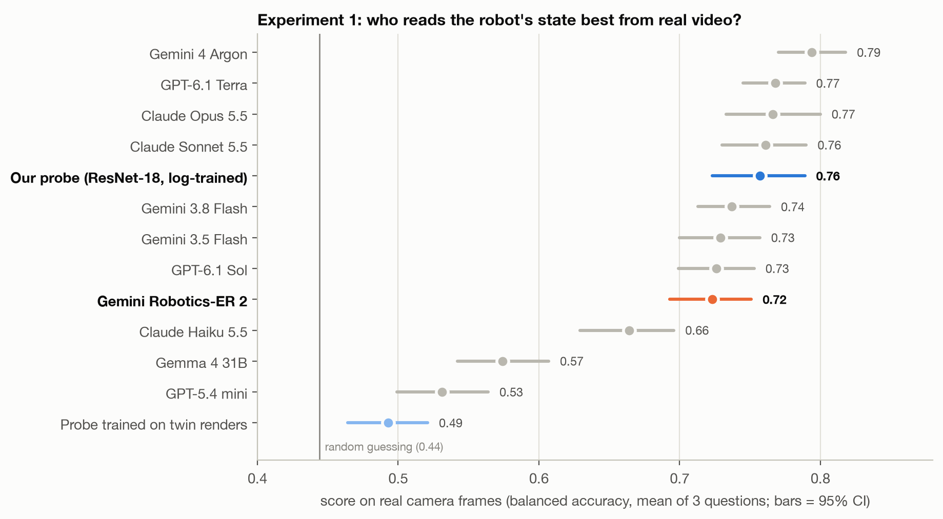
The top five are statistically tied. Gemini 4 Argon leads at 0.79 [0.77, 0.82], followed by GPT-6.1 Terra and Claude Opus 5.5 (0.77), Claude Sonnet 5.5 (0.76) and our probe (0.76 [0.72, 0.79]).
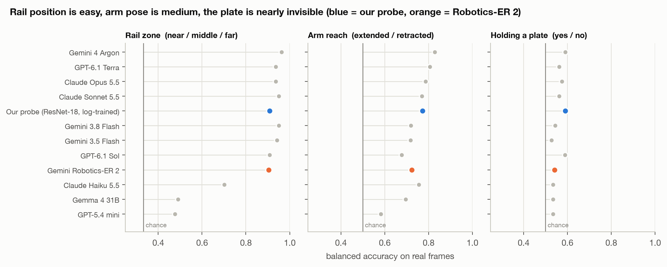
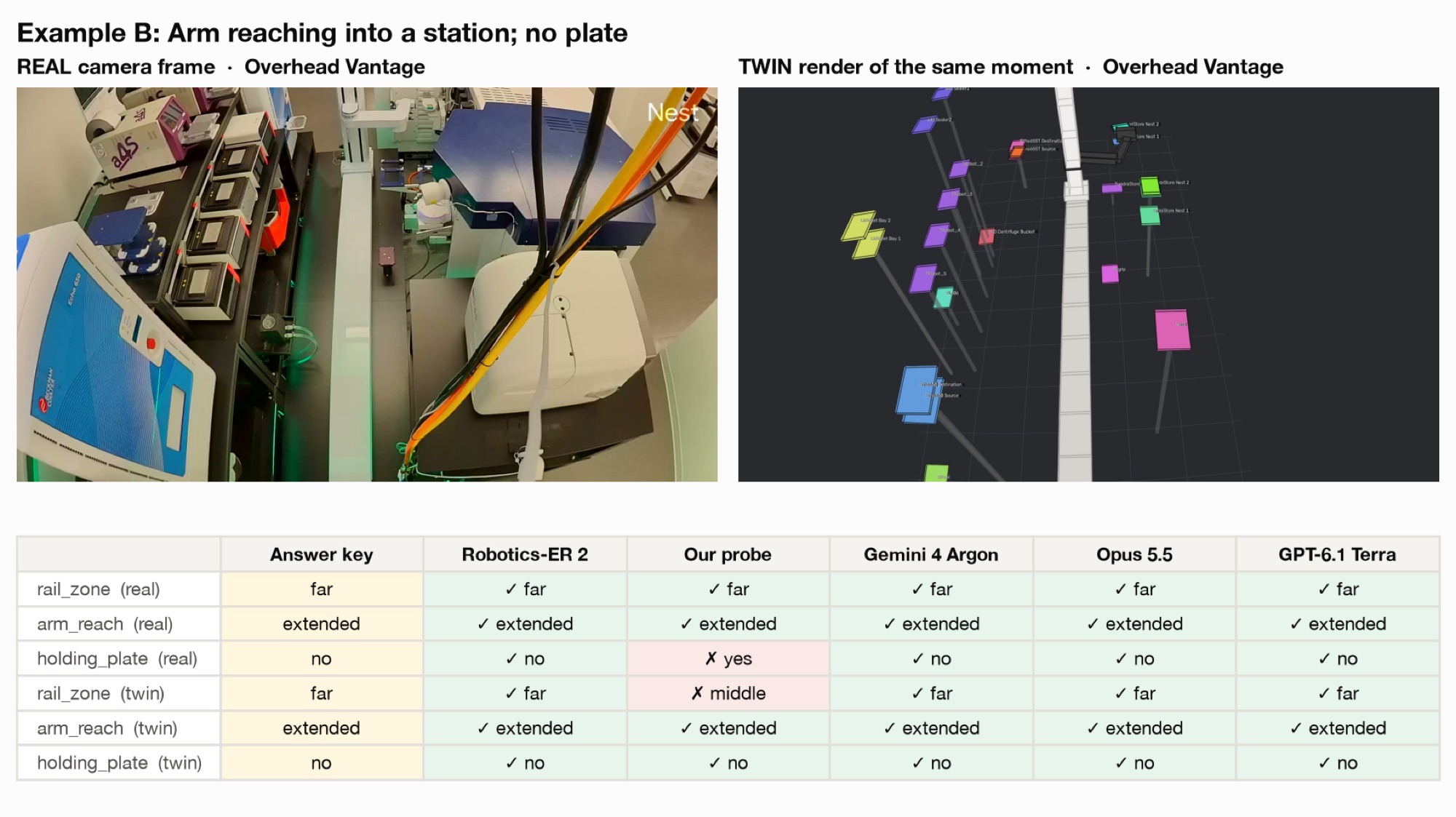
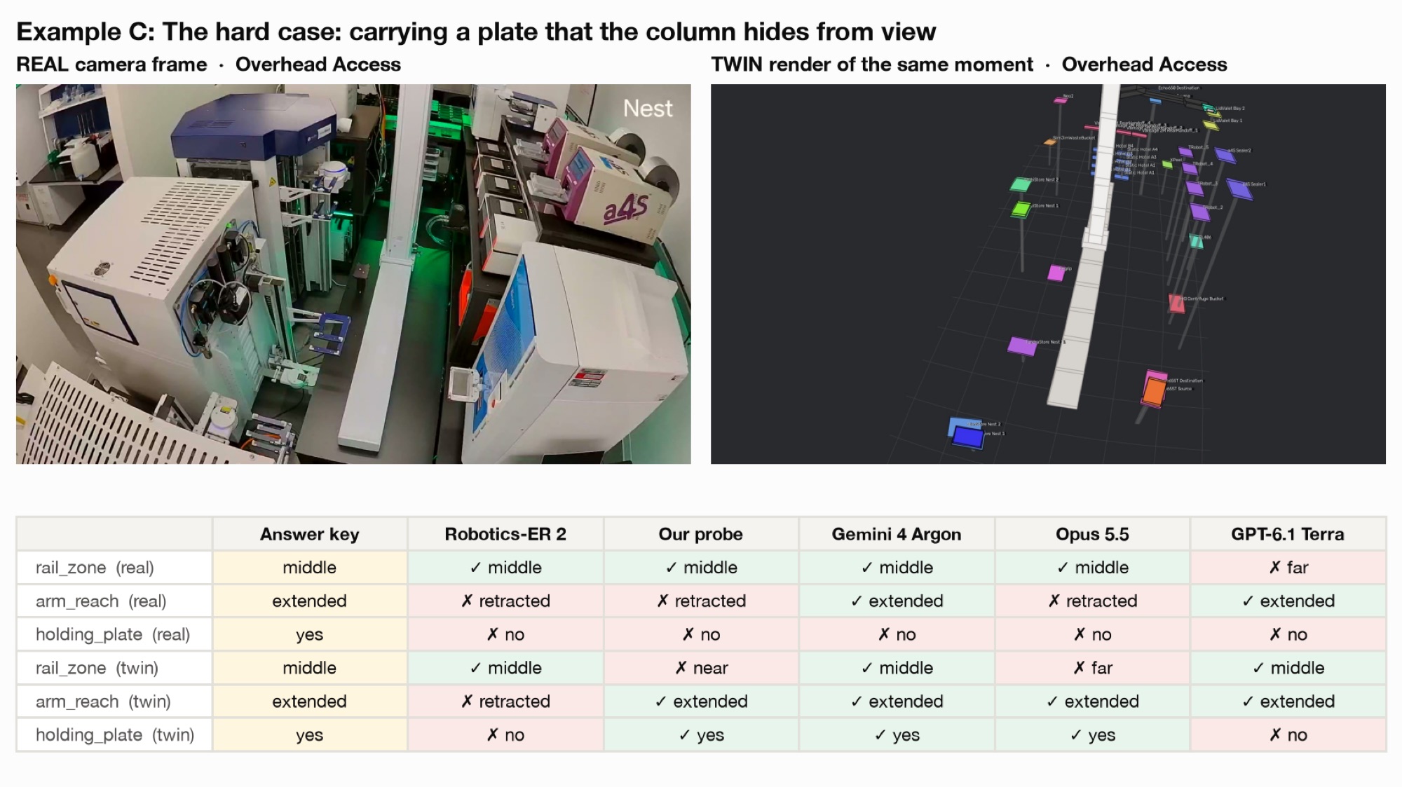
Rail zone is largely solved: frontier models score 0.90–0.96 and our probe 0.91. Arm reach is harder (0.68–0.83), because the arm is thin, seen at steep angles and stretched by the fisheye lens. Plate held is near chance for every model (at most 0.59). When a plate is held, the gripper is usually hidden behind the column or squashed at the image edge. This is a limit of where the cameras are, not of the models or the simulator.
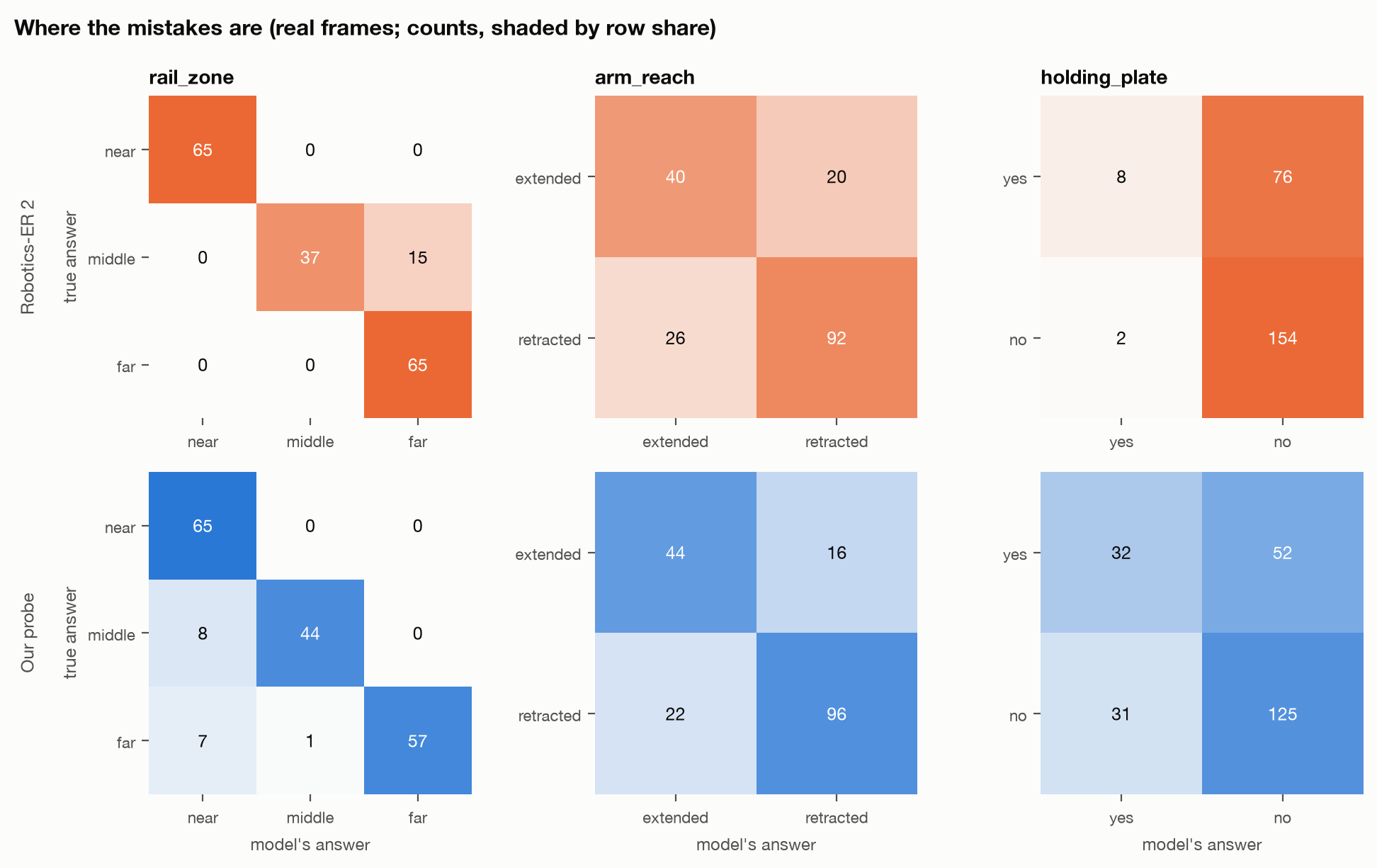
ER-2 never confuses near with far; its rail errors are middle predicted as far. On plate held it answered “yes” for 10 of 240 frames, against 84 true positives. Our probe answered “yes” 63 times, with 32 true positives.
Our simulator ranks frontier models the way reality does
If the twin ranks models in the same order as real footage, we can use it to evaluate conditions we have never filmed, such as rare faults or new layouts. We rendered every test moment from the same calibrated cameras and scored every model on the renders.
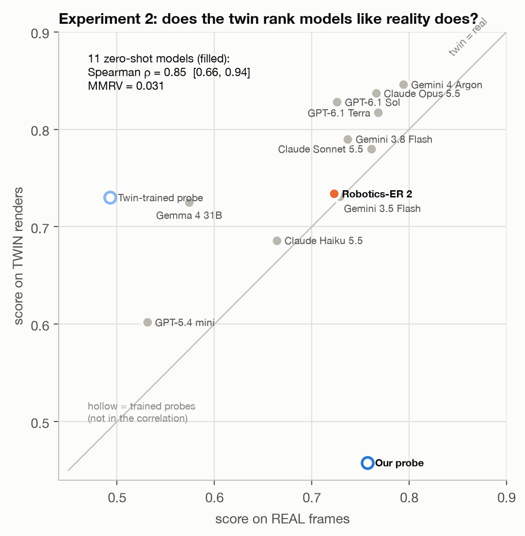
Across the 11 zero-shot models, twin and real scores correlate at Spearman ρ = 0.85 [0.66, 0.94], with an MMRV of 0.031: when the twin misorders two models, their real scores differ by about 3 points, roughly the size of our confidence intervals. This is in the range SIMPLER reports for its visual-matching variant. The twin is easier than reality overall, and neighbouring models can swap places, so it preserves the coarse ranking rather than the fine one.
Ranking well is not the same as training well
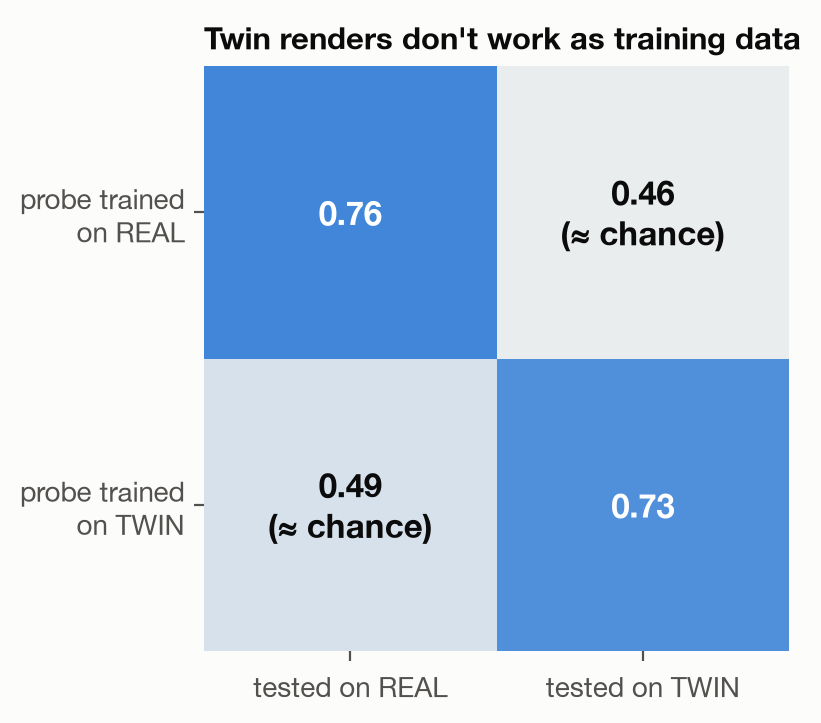
A probe trained on our geometric twin’s renders is at chance on real footage: 0.49 overall, with rail zone 0.44, arm reach 0.50 and plate held 0.54. This is the same twin that ranks frontier models at ρ = 0.85.
Large pretrained models bring enough visual knowledge to read both real frames and renders, so the twin can rank them. A model that learns its perception from the twin learns features that only exist in the renders. For our purposes this is the most important result in the study. Ranking agreement of the kind SIMPLER measures shows that a simulator is a sound evaluation proxy. It does not show that the simulator is a sound training environment, and in our case the two come apart completely. A simulator intended for robot learning has to be validated by transfer.
Hill-climbing simulator realism
Transfer to real footage gives us a metric we can climb. We train the same probe on a sequence of increasingly realistic simulator renders, and score each one on the same 240 held-out real frames. To avoid overfitting that test set, design choices are made using the training runs only, and each final configuration is scored on the test frames once.
Learning the robot’s appearance from video
Our most realistic rung replaces the twin’s rendered robot with an articulated Gaussian splat: a 3D representation made of many small, semi-transparent Gaussians whose position, shape, colour and opacity are optimised to reproduce real frames.
Splats are normally reconstructed from many viewpoints, and our cameras never move. The robot, however, moves through thousands of logged poses, which gives us the equivalent multi-view signal for the robot itself. We built the splat around the logs:
- One set of Gaussians per rigid link: column, carriage, upper arm, forearm, wrist, and a plate that appears only when the log records the robot holding one.
- Each link is posed by its logged joint state through the twin’s forward kinematics.
- Appearance is optimised against real frames, with a learned per-link pose correction to absorb errors in the twin’s geometry.
The static scene is a background plate: the per-pixel median over hundreds of frames, ignoring pixels near the robot. Like the probes, the splat is fitted leave-one-run-out.
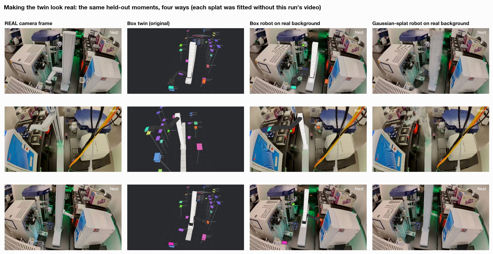
We also apply background randomisation, compositing each training pose over a background drawn at random from the training runs.
Domain randomisation
The splat’s renders are still cleaner and more uniform than real footage. Following the sim-to-real literature, we tested seven standard techniques on top of the splat, declared in advance: - Pixel-level domain randomisation (Tobin et al. 2017; Tremblay et al. 2018): photometric (brightness, contrast, saturation, colour gain, gamma, blur, sensor noise, JPEG compression), geometric (small random shifts, scalings and rotations of the robot layer, standing in for calibration error), and robot-appearance randomisation. - Feature-level adaptation using unlabelled real footage from the training runs: per-domain normalisation (AdaBN; Li et al. 2016) and CORAL (Sun & Saenko 2016). - Class-balanced self-training on that footage (CBST; Zou et al. 2018).
To pick a configuration without touching the test set, we trained each one on renders from one training run and scored it on real footage from another, then chose the best average score.
| Configuration (validation on training runs) | Overall | Rail zone | Arm reach | Plate held |
|---|---|---|---|---|
| Splat, no randomisation | 0.465 | 0.39 | 0.50 | 0.50 |
| + photometric randomisation | 0.565 | 0.55 | 0.61 | 0.53 |
| + photometric + geometric randomisation (chosen) | 0.594 | 0.66 | 0.59 | 0.53 |
| + robot-appearance randomisation | 0.573 | 0.61 | 0.58 | 0.53 |
| + per-domain normalisation | 0.504 | 0.47 | 0.54 | 0.50 |
| + CORAL | 0.479 | 0.40 | 0.53 | 0.51 |
| + self-training | 0.528 | 0.54 | 0.55 | 0.50 |
| + self-training + CORAL | 0.478 | 0.40 | 0.53 | 0.51 |
| Reference: trained on real labelled footage | 0.707 | 0.81 | 0.71 | 0.60 |
We picked photometric plus geometric randomisation.
Results
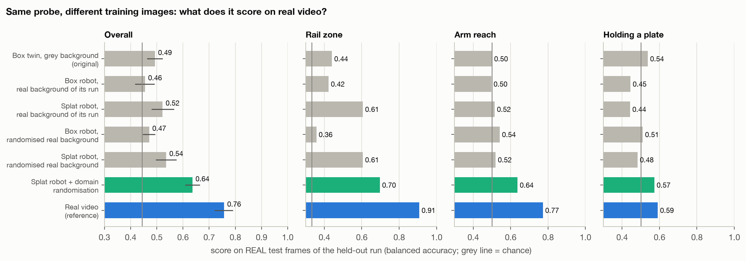
| Training images | Overall (real) | Rail zone | Arm reach | Plate held |
|---|---|---|---|---|
| Geometric twin | 0.49 | 0.44 | 0.50 | 0.54 |
| Splat robot | 0.54 [0.50, 0.57] | 0.61 | 0.52 | 0.48 |
| Splat robot + domain randomisation | 0.64 [0.61, 0.66] | 0.70 | 0.64 | 0.57 |
| Real footage (reference) | 0.76 | 0.91 | 0.77 | 0.59 |
Two steps up the ladder, learning the robot’s appearance from video and then adding domain randomisation, raise real-footage accuracy from 0.49 to 0.64 (+0.14, 95% CI [+0.10, +0.19]). That closes 54% of the gap to training on real footage, without using any real labels, and the gains are significant on both rail zone and arm reach.
Conclusion
At Gamow Labs, we are building toward autonomous experimentation: robots that can run, monitor and recover lab work on their own. Getting there means training on our workcell, and iterating at scale means having a simulator that confidently mirrors reality.
This work is a step toward that simulator. The robot’s own logs let us check our simulator against reality without labelling anything by hand. We found that it already compares models the way the real cell does, and that looking right is not the same as being good to learn from. Most importantly, we found that we can make the simulator more realistic and see that improvement show up on the real cell.
That gives us a clear way forward. Every change to the simulator can be tested against real footage, so we can keep closing the gap between simulation and reality until what we learn in simulation holds up in the lab.